The reflection of
light from real surfaces has been the subject of substantial theoretical and
experimental work. The
experimental results are close to the Phong illumination model with some
differences. These differences are that the intensity of the specular
reflection varies with the direction of the
light source and the angle of peak specular reflection is not always
exactly at the angle of incidence. In 1967 Torrance and Sparrow [7] derived a theoretical model to
explain these effects. Their theoretically predicted functions
and the experimentally measured data are very close. In this section we derive
the Torrance Sparrow highlight function in terms of the vectors N, I, H
and E, all of which are assumed to be normalized.
| H = (L + E) / 2 where H is the normal to a perfect specular reflector oriented such that the incident light is reflected to the viewer's eye (E). | |
The surface being simulated is assumed to be composed of a collection of mirror like micro facets that are oriented in random directions on the surface. The specular component of the reflected light is assumed to come from reflection from the facets oriented in the direction of H. The specular reflection is then a combination of four factors:
| S = DGF/(N·E) | D is the distribution function of the directions of the micro facets on the surface. G is the amount by which the facets shadow and mask each other. F is the Fresnel reflection law,. |
The light reflected specularly in my given direction can come only from the facets oriented to reflect the light in that direction. That is, the facets whose local normal vectors point in the direction of H. The first term in the specular reflectance is the evaluation of the distribution of the number of facets pointing in that direction. Note that the Phong model ignores the G and F terms and uses D = (cos a)n
| The distribution used by Torrance and Sparrow was a simple Gaussian:
D = e-(ac2)^2 |
D2 is the proportionate number of facets oriented at an angle a from the average normal to the surface. The factor c2 is the standard deviation for the distribution and is a property of the surface being modeled. Large values yield dull surfaces and small values yield shiny surfaces. We are interested in the number of facets pointing in the direction of H so the angle a is Cos-1'(N·H). |
| Blinn used this formula because it gave similar results to
the Gaussian result above, was easier to compute, and had some
experimental justifications:
|
This formula is based on modeling the microfacets as ellipsoids of revolution and c3 is the eccentricity of the ellipsoids. It is 0 for very shiny surfaces and 1 for very diffuse surfaces. |
Since the intensity is proportional to the number of facets pointing in the H direction, we must take into account that the observer sees more of the surface area when the surface is tilted. The increase in area is inversely proportional to the cosine of the angle of tilt. The tilt angle is is the angle between the average surface normal, N, and the eye, E. This explain, the division by (N·E).
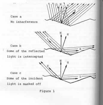
| Some of the facets shadow each other, thus reducing either
the incident or the reflected light. The
degree to which this shadowing occurs is called the ""geometrical
attenuation factor", G. It is a value from 0 to 1 representing the proportionate amount of
light remaining after the masking or shadowing has taken place.
Calculation of G assumes that the micro facets exist in the form of V
shaped
grooves with the sides at equal but opposite angles to the average surface
normal. We are interested only in grooves where one of the sides points in
the specular direction H. For differing positions of the light source and
eye position we can have one of three cases illustrated in Figure 1. From
geometry we can derive the following:
For Case a Ga = 1.0 For Case b Gb = 2(N·H)(N·E)/(E·H) For Case c Gc = 2(N·H)(N·L)/(E·H) Then G = min (Ga, Gb, Gc) |
_
 |
| The Fresnel reflection gives the fraction of light incident on a facet that is reflected rather than absorbed. It is a function of the angle of incidence of the light (f = cos-1 (L·H) = cos-1 (E·H)) and the index of refraction of the substance. For metals, with a large index of refraction, F is nearly constant at about 1. For non-metals with index of refraction small (about 1-2) F is near zero at f = 0 and approaches 1 at f = p/2. |  |
||||||||||||||||||||||||||||||||||||||||||||||||||||||
| Using some trigonometric identities it can be shown that the Fresnel formula can be expressed as show in the adjacent formula. Note this expression must be divide by 2.0 to give the correct result. For an incident angle of 90 degrees (c=0) the result is 2/2 = 1.0. |  |
||||||||||||||||||||||||||||||||||||||||||||||||||||||
|
Here are some values of F for different materials. Glass has an index of refraction of about 1.5 and a metal has an index of refraction of about 200 (for aluminium). For an index of refraction of 200 the F value is greater than 0.9 for all angles.
|
Magnesium Oxide ceramic has an index of refraction of 1.8
|
The hemisphere is the diffuse reflection intensity and the bump is the specular reflection intensity. Note that the two models are almost identical for an incident angle of 30 degrees. Both specular bumps are perfectly aligned with H. In the figure below, the incident angle is 70 degrees. Notice that the Blinn (Torrance-Sparrow) model is much more intense and not aligned with H.
|
Comparison with Simulated Aluminum Using the experimentally measured values for aluminum :
|
 |
|
Comparison with Magnesium Oxide Ceramic Using the experimentally measured values for aluminum :
|
 |
![]()
![]() Go to
Local Illumination
Model main page.
Go to
Local Illumination
Model main page.
![]() Go to HyperGraph
home page.
Go to HyperGraph
home page.